
What are breadboards
This is a beginner's guide to electronics. It is a simple explanation of breadboards and how they work. Try online breadboard circuits before you go out and buy a breadboard.
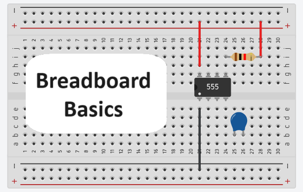
Breadboards are used to make electronic circuits. They are place holders for components in a circuit.
How do you use a breadboard
Electronic components are inserted into holes in the breadboard. Small wires called jumpers are used to connect inserted components. When the circuit is fully connected, it forms a closed loop through which current flows.
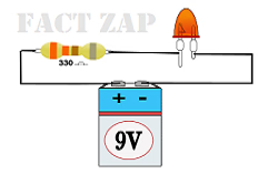
Simple circuit for beginners
This circuit makes a light glow by connecting power supply to a light (Light Emitting Diode or LED). A resistor is used to filter excess current and protect the LED.
To replicate the same on a breadboard, we begin by inserting components. Jumper wires are used for connections. Battery is connected to the breadboard. LED glows. If the LED does not glow, connections are checked to make sure it is a closed loop.
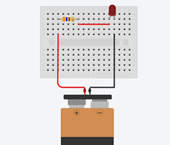
breadboards make it easy to place components and make connections. Changes can be made many times to fine tune the circuit. Electrical engineers use breadboards to test new circuits before making printed circuit boards.
How breadboards work
Take a look inside a breadboard
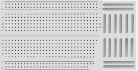
Breadboards have three layers. Top layer is plastic with holes. Metal leads of resistors, capacitors and ICs are inserted in to these holes.
Under it, is a layer of metal strips. Metal leads of components placed on the breadboard touch the metal strips.
Power rails have horizontal metal strips. Rest of the breadboard has vertical metal strips. Components are interconnected by placing them directly below or on top in one vertical column.
Horizontal metal strips at the top and bottom are called power rails. They are connected to the supply and ground terminals of the power supply.
Most breadboards have dividers in between. Divider separate the breadboard in to two sections. Both sections have no interconnections. They are used to insert ICs and switches.
Parallel circuits in breadboards
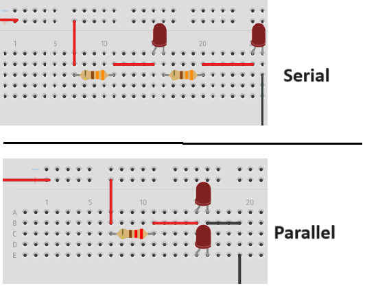
If a ciruit has two LEDs wired one after the other, it is called serial circuit. If the LEDs are connected parallel to each other such that they receive the same amount of current at the same place in the circuit, it is a parallel circuit.
In a serial circuit, voltage changes for every component in the circuit. But in parallel circuits, voltage is the same for all components connected in parallel.
Virtual breadboard
Virtual breadboards help beginners learn circuit design. Virtual breadboards are simulations of real breadboards. They can be used on computers and mobile devices. They come with drag and drop features and a library of electronic components to choose from.
Students drag and drop a breadboard in to the work area. Then add electronic components to the breadboard, draw connections between them. The app shows the working circuit. It points out mistakes and gives warnings.
Beginners find it helpful to use virtual breadboard first, before they start hands on with real breadboard circuits.
TinkerCAD
TinkerCAD is a free application for making circuits online. It has step by step tutorials on circuits, 3D printing and Arduino programming. For beginners, TinkerCAD is a good place to start self learning circuits. Signing up for free is all that it takes.
Fusion360 and KiCAD are free tools for experienced designers. Industries use paid and licensed tools with advanced simulation capabilities.
Start tinkering with TinkerCAD and enjoy learning circuit designing. Before long, you will be an experienced PCB designer. Start learning now.